Here is another guy that is having the same issues and he has a few threads on the same project but at the bottom of this page is where I explain what is happening The Back Shed: help with circuit Here are two threads that discuss this issue about that you are describing.ĭo read through this thread as this is the beginning and the good stuff comes in at about post #60 and later,

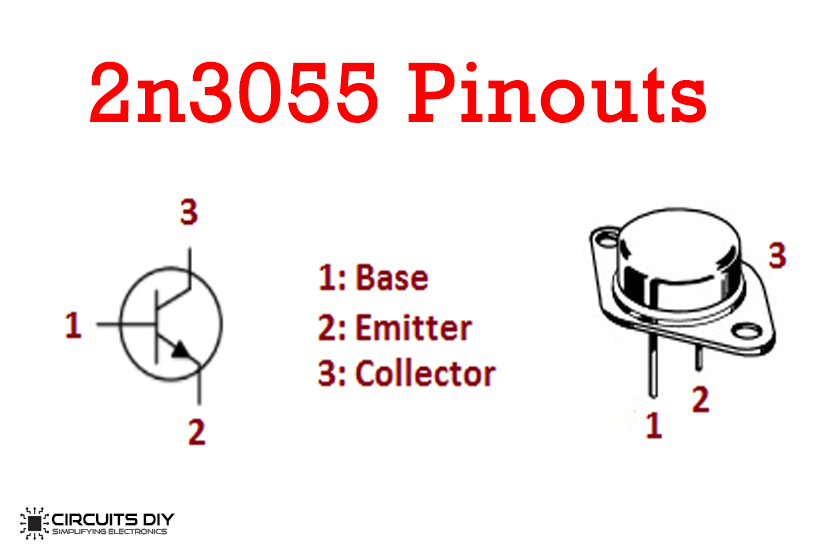
Lack of base/emitter resistors for load sharing purposes. Problem is as soon as I apply any load what so ever both 2n3055 transistors instantly blow and there's 30v at the output.ģ. The output voltage remains steady and variable from 0 to about 15 volts. The 2n3055's are in a common collector (emitter follower) configuration with no emitter resistors or base resistors. I have a lm317 variable voltage regulator I.C driving the bases of 2n3055 pass transistors. I have about 500uf of capacitance (no where near enough I know I need about 30,000) I have a 57v transformer that looks like it's good for about 20 amps, I have the center tap half wave rectified to give me 30v. This post though is about a power supply I have made. This isn't specifically about audio but I am very much an audio enthusiast and will no doubt be posting asking about some questions for a guitar amp I am in the process of designing. So, you should a Speaker protector circuit, too.īesides this, we introduce these easy projects. Sometimes, you may like them.Hey guys I'm new here this is my first post. It may cause oscillated noise more easily. Because power transistors can tolerate a voltage of no more than 60V. It makes the voltage of the power supply up to 38.17V. Change the voltage of the secondary transformer to 27V CT 27V 3A.Because they are small size but have high power. You may use TIP3055 and TIP2955 instead of 2N3055 and MJ2955.But if you use LF351, low-cost high-speed JFET input operational amplifier. 2N3055 Amplifier Circuit with PCB | 60W.See the prototype of 50W amplifier circuit. Oscillation or noise within the circuit.Check the B-E extension wires of the power output Transistors.Transistors – Q1 and Q3 may be broken in an open circuit.ģ.


Use a voltmeter to measure the voltage at ZD1 and ZD2.Connect the power supply to the circuit.Why does not put the transistors? Because while the transistors are working. Except, do not put IC1(LF351) and power output transistors Q3(2N3055) and Q4(MJ2955).


 0 kommentar(er)
